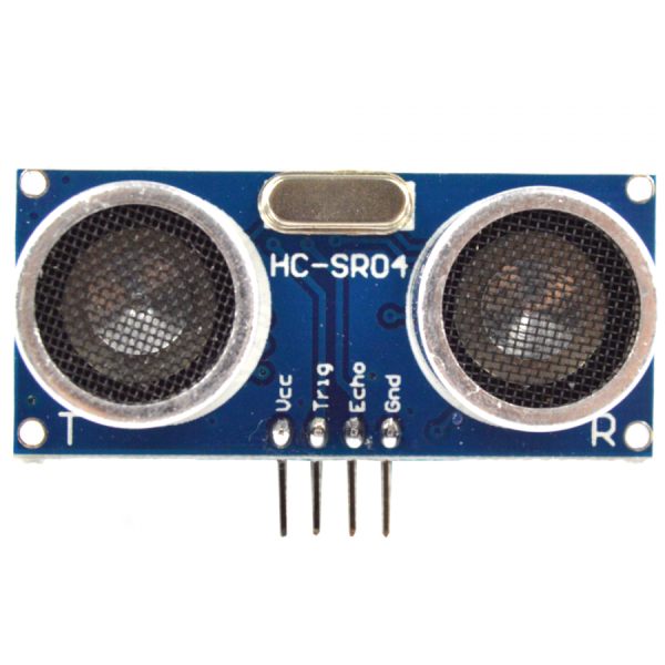
The basic principle of work:
- Using IO trigger for at least 10us high-level signal,
- The Module automatically sends eight 40 kHz and detect whether there is a pulse signal back.
- IF the signal back, through high level , time of high output IO duration is the time from sending ultrasonic to returning. Test distance = (high level time×velocity of sound (340M/S) /2
Specifications:
- Power supply :5V DC
- Quiescent current : <2mA
- Effectual angle: <15°
- Resolution: 3 mm
- Sensing distance: 0.75in (2cm) to 13ft (4m)
- More precise measurements with ranges up to 6.5ft (2m) away
- Resolution : 0.3 cm
There are 4 pins out of the module : VCC , Trig, Echo, GND. So it's a very easy interface for controller is to use it ranging. The process is: pull the Trig pin to high-level for more than 10us impulse , the module will start ranging ; finish ranging , If you find an object in front , Echo pin will be high level , and based on the different distance,it will take the different duration of high-level. So we can calculate the distance easily :
How Does it Work?
The ultrasonic sensor uses sonar to determine the distance to an object. Here’s what happens:
- the transmitter (trig pin) sends a signal: a high-frequency sound
- when the signal finds an object, it is reflected and
- the transmitter (echo pin) receives it.

The time between the transmission and reception of the signal allows us to know the distance to an object. This is possible because we know the sound’s velocity in the air.
Sensor
 Pins
Pins
- VCC: +5VDC
- Trig : Trigger (INPUT)
- Echo: Echo (OUTPUT)
- GND: GND
Arduino with HC – SR04 Sensor
This sensor is really cool and popular among the Arduino tinkerers. So, here we provide an example on how to use the HC-SR04 ultrasonic sensor with the Arduino. In this project the ultrasonic sensor reads and writes the distance to an object in the serial monitor.
The goal of this project is to help you understand how this sensor works. Then, you can use this example in your own projects.
Parts Required
Schematics
Follow the next schematic diagram to wire the HC-SR04 ultrasonic sensor to the Arduino.
The following table shows the connections you need to make:
| Ultrasonic Sensor HC-SR04 | Arduino |
| VCC | 5V |
| Trig | Pin 11 |
| Echo | Pin 12 |
| GND | GND |
Source code
Upload the following code to your Arduino IDE./* * created by Rui Santos, http://randomnerdtutorials.com * * Complete Guide for Ultrasonic Sensor HC-SR04 * Ultrasonic sensor Pins: VCC: +5VDC Trig : Trigger (INPUT) - Pin11 Echo: Echo (OUTPUT) - Pin 12 GND: GND */ int trigPin = 11; //Trig - green Jumper int echoPin = 12; //Echo - yellow Jumper long duration, cm, inches; void setup() { //Serial Port begin Serial.begin (9600); //Define inputs and outputs pinMode(trigPin, OUTPUT); pinMode(echoPin, INPUT); } void loop() { // The sensor is triggered by a HIGH pulse of 10 or more microseconds. // Give a short LOW pulse beforehand to ensure a clean HIGH pulse: digitalWrite(trigPin, LOW); delayMicroseconds(5); digitalWrite(trigPin, HIGH); delayMicroseconds(10); digitalWrite(trigPin, LOW); // Read the signal from the sensor: a HIGH pulse whose // duration is the time (in microseconds) from the sending // of the ping to the reception of its echo off of an object. pinMode(echoPin, INPUT); duration = pulseIn(echoPin, HIGH); // convert the time into a distance cm = (duration/2) / 29.1; inches = (duration/2) / 74; Serial.print(inches); Serial.print("in, "); Serial.print(cm); Serial.print("cm"); Serial.println(); delay(250); }


